Bluetooth Classic from scratch on an SDR: play an MP3 on a headset.
A Bluetooth BR/EDR controller written from the radio samples up, in the l8 language: GFSK modem, baseband, link manager and a standard HCI in the FPGA of a software-defined radio. No Bluetooth chip is involved on our side; the peer is an ordinary Bluetooth device.
The hardware: a LimeSDR Mini 2.0 -- a Lattice ECP5 FPGA (LFE5U-45) beside an LMS7002M radio chip -- and an FT2232H JTAG cable on its JTAG header. On the PC: Python, the Bumble host stack, ffmpeg. The bitstream is built with yosys and nextpnr-ecp5.
The board is a Bluetooth controller behind a standard HCI: a PC program finds the devices in range and plays an audio file on one of them. This works and is measured -- against a Bluetooth dongle at arm's length, over both the JTAG and the USB cable.
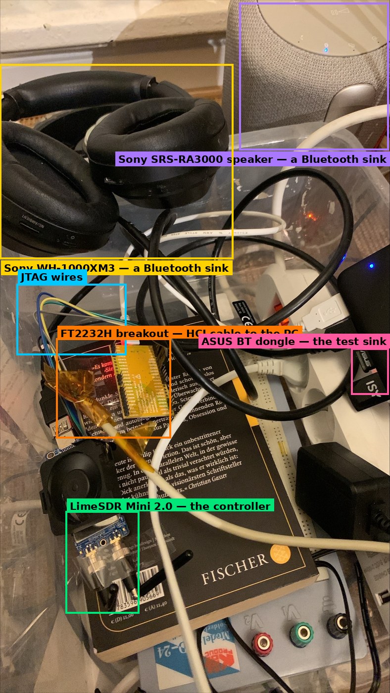
The bench: the LimeSDR Mini 2.0 is the controller; the FT2232H breakout carries the HCI to the PC over the JTAG wires; the Sony speaker, the Sony headset and the ASUS dongle are Bluetooth sinks it plays to. Beside it, with sound: the speaker playing an MP3 sent by the board (13 s).
l8bluetooth-dist.tar.gz --
the two FPGA bitstreams and the PC programs. With a LimeSDR Mini 2.0,
openFPGALoader, Python (pip install bumble pyusb) and
ffmpeg:
make check                                          # are the tools, Python packages and board ready?
make deps                                           # install the Python packages (bumble, pyusb)
make prog                                           # program the controller over JTAG (TUNE=osc, the default)
make prog TUNE=lowif                                #   ... or with low-IF tuning, or TUNE=digital (see below)
make bridge                                         # the HCI on TCP 127.0.0.1:9001 (leave running)
and in a second terminal:
make scan                                           # the devices in range, and the ones paired before
make pair ADDR=AA:BB:CC:DD:EE:FF                    # once per device, in pairing mode: keeps its key
make play ADDR=AA:BB:CC:DD:EE:FF FILE=song.mp3      # connect and stream
make forget ADDR=AA:BB:CC:DD:EE:FF                  # drop a device's key
TUNE picks one of the three ways to
tune described further down -- osc (the
synthesizer hops), lowif (it hops 1 MHz beside the channel,
digital mixers shift the signal), digital (it stands,
digital mixers hop). All three are in the same bitstream;
make tune TUNE=.. changes it without reprogramming. A
device shows in a scan only while it is discoverable (pairing mode);
once paired it is reached by its address.
The archive also holds a test image with the whole stack on the chip
(run_tune.py ADDR osc | lowif | digital: a 440 Hz tone, no
PC host stack) and the emitted Verilog of every image.
What is in the archive:
| file | what it is |
|---|---|
README.md |
the instructions: dependencies, the commands, the tuning modes |
Makefile |
the shortcuts: check, deps,
prog, prog-usb, tune,
bridge, bridge-usb, scan,
pair, forget, play |
check.py |
make check: are the tools, the Python packages and the
board there |
requirements.txt |
the Python packages (bumble, pyusb) |
firmware/top_hcic.bit |
the controller, its HCI over the JTAG cable |
firmware/top_hciu.bit |
the controller, its HCI over the board's USB data channel |
firmware/top_tune.bit |
the tuning test image: the whole stack on the chip, plays a 440 Hz tone |
bt_play.py |
the player: scan, pair,
forget, play (Bumble host stack, ffmpeg's SBC
encoder) |
jtag_hci_bridge.py |
the HCI bridge over JTAG (TCP 127.0.0.1:9001) |
hci_bridge.py |
the HCI bridge over USB |
jtag_host.py |
the JTAG cable's driver (FT2232H, pyusb), used by the bridge and the tuning tools |
ft601_pipe.py, lms64c_host.py |
the USB data channel's driver, used by
hci_bridge.py |
tune_set.py |
sets the tuning mode on a loaded image: osc,
lowif, digital
(make prog TUNE=.., make tune) |
run_tune.py |
the tuning test: loads top_tune.bit, pages a device,
plays the tone in one of the three modes |
tune.json |
each tuning mode's register writes and run-time word |
lms_port.py |
reads and writes the radio chip's registers over JTAG (used by the two tuning tools) |
verilog/README.md |
how to rebuild the bitstreams |
verilog/jtag/, verilog/usb/,
verilog/tune/ |
the three images as emitted Verilog: top.v (the board),
the design, top.lpf (pins), Makefile,
pincheck.py + top.pins (the pin-timing
check) |
keys/ |
made by the first pairing: your link keys. Not in the archive; do not share it |
The archive's README.md lists the dependencies and how
to install them, and has the full instructions, including the USB cable
as the HCI carrier (firmware/top_hciu.bit with
hci_bridge.py).
Bluetooth Classic (BR/EDR, "Basic Rate / Enhanced Data Rate") is the Bluetooth that carries audio to speakers and headsets. It is a stack of layers; a phone or a PC splits it in two at the HCI (Host Controller Interface): the controller below -- a chip, here our FPGA -- does everything with a deadline in microseconds, the host above -- the operating system, here Bumble on the PC -- everything else.
┌─ HOST -- the PC: Bumble, Python ───────────────────────────┐
│ A2DP     the audio profile: who is source, who is sink     │
│ AVDTP    streams: discover, configure, open, start         │
│ SBC      the audio codec (ffmpeg encodes it)               │
│ SDP      "which services do you offer?"                    │
│ L2CAP    channels, segmentation of long messages           │
└────────────────────────────────────────────────────────────┘
                    ▲ ▼  HCI: commands, events, ACL data (H4 bytes over the pipe)
┌─ CONTROLLER -- the board ──────────────────────────────────┐
│ LMP      the link manager: features, pairing, encryption   │
│ baseband packets, ARQ, hopping, inquiry, paging, E0 cipher │
│ modem    bits <-> GFSK I/Q samples, 1 Mbit/s               │
│          FPGA, l8                                          │
└────────────────────────────────────────────────────────────┘
                    ▲ ▼  I/Q samples, 4 per bit (LML bus, DDR)
┌─ RADIO ────────────────────────────────────────────────────┐
│ LMS7002M: mixers, filters, ADC / DAC, 2.4 GHz synthesizer  │
└────────────────────────────────────────────────────────────┘
How many devices share one band. The 2.4 GHz band is cut into 79 channels of 1 MHz (2402 .. 2480 MHz). A connection -- a piconet: one Central and up to seven Peripherals -- does not stay on a channel: it hops 1600 times a second along a pseudo-random sequence computed from the Central's address and clock. Time is cut into 625 us slots; the Central transmits in even slots, the Peripheral it addressed answers in the next. A packet may take 1, 3 or 5 slots, and the radio stays on the packet's first channel for all of them.
channel
     │               ┌────┐
  78 │               │ C  │
     │               └────┘
     │                                                  ┌────┐
  64 │                                                  │ P  │
     │                                                  └────┘
     │        ┌────┐
  52 │        │ P  │
     │        └────┘
     │                                           ┌────┐
  45 │                                           │ C  │
     │                                           └────┘
     │ ┌────┐
  31 │ │ C  │
     │ └────┘
     │                      ┌──────────────────┐
   3 │                      │    P 3 slots     │
     │                      └──────────────────┘
     └┴──────┴──────┴──────┴──────┴──────┴──────┴──────┴──────┴▶ time
         0      1      2      3      4      5      6      7   slot (625 us each)

  C: the Central sends (even slots)     P: the Peripheral it addressed answers in the next slot
  the 3-slot packet stays on its first channel; the hop after it is the one the clock says
Two piconets nearby hop along two different sequences. Now and then both land on the same channel in the same slot: one packet is garbled, its checksum fails, the receiver does not acknowledge it, and it is sent again in a later slot (ARQ). Wi-Fi sits still on 20 MHz of the same band; Adaptive Frequency Hopping (AFH, not built here) lets a piconet leave those channels out.
How the two stay in step. Nobody announces a hop. Both sides put the same two numbers -- the Central's address and the Central's clock -- into the same public selection function and get the same channel for every slot. The address is fixed; the clock is the part that needs care:
| what | limit (Core 5.4 Vol 2 Part B 2.2.5) |
|---|---|
| a device's slot timing against the ideal | 20 ppm |
| one packet start against the average | 1 us |
| the receiver's window around the expected start | 10 us early .. 10 us late |
| time between a packet's end and the next slot | about 259 us after a full one-slot packet |
In that last gap the radio must retune: it has to be on the new channel before the slot begins, and it must not leave the old one before the packet's tail has left the antenna. On this board a hop is seven SPI transactions to the LMS7002M's synthesizer and a settling wait: at most 157 us at 2.5 MHz SPI, 105 us at 5 MHz, measured on a live link.
A packet. Every packet starts with a 72-bit access code whose 64-bit sync word is derived from the Central's address -- a receiver finds packets of its piconet by correlating against it -- then a 54-bit header (the 18 bits of address, type, flow, ARQN and SEQN sent three times), then the payload.
┌─────────────────────────────────────┐    ┌────────────────────────────────┐    ┌─────────────────────────────┐
│ ACCESS CODE  72 bit                 │ ─▶ │ HEADER  54 bit                 │ ─▶ │ PAYLOAD  0 .. 2745 bit      │
│ preamble 4  sync word 64  trailer 4 │    │ 18 bit x 3 (FEC 1/3): LT_ADDR, │    │ header, data, CRC 16        │
│ "is this my piconet?"               │    │ TYPE, FLOW, ARQN, SEQN, HEC    │    │ FEC 2/3 (DMx) or none (DHx) │
└─────────────────────────────────────┘    └────────────────────────────────┘    └─────────────────────────────┘
Finding a device and connecting to it. A device that wants to be found listens in inquiry scan on a slow hop sequence of its own; one that may be connected listens in page scan. Finding is the inquiry: the PC's list of devices. Connecting is the page: the Central sends the target's ID on the hops the target listens on until it answers, then hands it its address and clock in an FHS packet -- from then on both hop together.
  PC (host)                 board (controller)                             the speaker
  ─────────                 ──────────────────                             ───────────
  Inquiry              ──▶  IDs (General IAC) on the inquiry hops     ──▶  in inquiry scan
  Inquiry_Result       ◀──  FHS: its address, class of device         ◀──  answers
  Create_Connection    ──▶  IDs (its address) on its page hops        ──▶  in page scan
                            its ID back; our FHS: our address, clock  ◀─▶  takes our clock
                            ── from here both hop by our clock ──
                            LMP: features, version, setup             ◀─▶
  Link_Key_Request     ◀─▶  LMP: pairing or the kept key (E1, E22)    ◀─▶  PIN 0000
                            LMP: encryption on (E0)                   ◀─▶
  Connection_Complete  ◀──
  L2CAP, SDP, AVDTP    ◀─▶  ACL data, every slot pair                 ◀─▶  A2DP sink
  SBC audio            ──▶  DH5 packets, 4 SBC frames each            ──▶  plays it
Security. Legacy pairing turns a PIN (here 0000) and two random numbers into a 128-bit link key (SAFER+-based functions E22, E21); the next time the key alone proves both sides (E1, challenge and response) and gives the encryption key (E3), and the E0 stream cipher encrypts every payload. The host keeps the key, so a device paired once does not have to be put in pairing mode again.
┌─ PC ───────────────┐      ┌─ bridge ───────────┐             ┌─ FPGA ECP5 ─────┐      ┌─ radio ──┐
│ bt_play.py         │  TCP │ jtag_hci_bridge.py │  JTAG / USB │ HCI (hci_bredr) │  I/Q │ LMS7002M │
│  scan / play FILE  │  ◀─▶ │   or hci_bridge.py │  ◀────────▶ │ link manager    │  ◀─▶ │ TX / RX  │
│ Bumble host stack  │      │ H4 on TCP 9001     │             │ pager, inquirer │      │ 2.4 GHz  │
│ ffmpeg: MP3 -> SBC │      └────────────────────┘             │ link, ARQ, E0   │      └──────────┘
└────────────────────┘                                         │ GFSK modem      │
                                                               └─────────────────┘

                                                                                          ~ ~ ~ ~ ~ ~
speaker or headsetThe cut is the one every Bluetooth product has: the controller below the HCI, the host above it. The controller is the FPGA, the host is a PC program.
| where | part | what it does |
|---|---|---|
| PC | apps/bt_play.py |
the menu: scan, pick a device, play a file |
| PC | ffmpeg | the file (anything ffmpeg reads) to SBC, 44.1 kHz joint stereo |
| PC | Bumble | L2CAP, SDP, AVDTP, A2DP; keeps the link keys |
| PC | jtag_hci_bridge.py |
the HCI's H4 byte stream between a TCP port and the board's pipe |
| HCI (H4 bytes over the pipe) | ||
| FPGA | hci/hci_bredr.l8 |
the HCI: commands in, events out, ACL data both ways |
| FPGA | link manager | LMP link setup; legacy pairing (PIN 0000) or a stored link key, both through SAFER+; E0 encryption |
| FPGA | pager, inquirer | starts a connection to an address; finds the devices in range |
| FPGA | baseband | hop selection, access codes, FEC, CRC, whitening, ARQ, multi-slot packets |
| FPGA | GFSK modem | modulator and demodulator on the I/Q samples |
| chip | LMS7002M | the 2.4 GHz radio, retuned for every hop |
Everything in the FPGA rows is l8 source; the image is
top_hcic, generated by tools/gen_central.py
with HCI=1 from the board image of the on-chip stack.
The H4 byte stream travels over a "pipe" of the board: a framed
channel of 16-bit words each way that a design gets from the board
description with one call (jtag.io). Today the carrier is
the JTAG cable:
| carrier | measured rate, each way |
|---|---|
| JTAG at 6 MHz TCK (the bridge's default) | 227 kB/s |
| JTAG at 30 MHz TCK | 713 kB/s |
A2DP with SBC needs about 30 kB/s, so the JTAG cable carries it with
room to spare. jtag_hci_bridge.py serves the stream on TCP
port 9001; Bumble opens tcp-client:127.0.0.1:9001 like any
other HCI transport.
USB pipe: works. The same HCI runs over the board's
USB (FT601) as well: the H4 bytes ride the LMS64C control channel
(command 0xB2), and design/limesdr_mini_2.0/hci_bridge.py
serves them on the same TCP port 9001, so the player does not know which
cable carries them. Image top_hciu
(gen_central.py with HCI=1 HUSB=1). Measured
2026-11-18 against the dongle: Bumble's power-on in 0.02 s; connect in
0.3 s; the 12 s stream of the same MP3 recorded by the dongle as 12.0 s
of audio, correlation 0.70 with the original -- the same figures as over
JTAG.
bt_play.py scan            # inquiry: a numbered list of the devices in range (address, class of device)
bt_play.py play ADDR FILE  # connect, stream FILE (anything ffmpeg reads)
bt_play.py                 # scan, show the list, ask which one, play ~/output.mp3
The first connection to a device pairs with PIN 0000 (the controller does it); Bumble stores the link key, and the next connection authenticates with that key -- the device need not be in pairing mode again.
In the repository, from
use/system/l8/communication/bluetooth/design/limesdr_mini_2.0:
HCI=1 python3 tools/gen_central.py 5C:F3:70:95:B3:DA top_hcic.l8   # the image's source (the host names the target at run time)
make TOP=top_hcic                                                  # l8i, yosys, nextpnr-ecp5 -> build_top_hcic/top.bit
make TOP=top_hcic prog                                             # load it into the FPGA over the JTAG cable
python3 jtag_hci_bridge.py                                         # H4 on 127.0.0.1:9001
python3 ../../apps/bt_play.py                                      # scan, choose, play
python3 ../../apps/bt_play.py pair AA:BB:CC:DD:EE:FF               # once per device, in pairing mode: keeps its key
python3 ../../apps/bt_play.py play AA:BB:CC:DD:EE:FF song.mp3      # from then on, no pairing mode needed
A device shows in a scan only while it is discoverable -- for a
speaker or headset that means pairing mode. Once paired it is reached by
its address, switched on is enough; scan lists the paired
devices it did not find as such. In the downloaded archive the same
steps are make prog, make bridge (leave it
running), and in a second terminal make scan,
make pair ADDR=..,
make play ADDR=.. FILE=...
2026-11-18. The peer: an ASUS USB dongle (BCM20702) running a Bumble A2DP sink, 10 cm from the board's antenna.
| step | result |
|---|---|
| scan | lists the dongle:
1 5C:F3:70:95:B3:DA (name not read) Audio/Video |
| connect | 1.2 s |
| stream | 349 kB of SBC, from a 3-minute MP3, in 12 s of real time |
| received at the peer | 12.0 s of audio; correlation 0.70 with the original at equal RMS (SBC is lossy) |
| disconnect | clean (reason 0x13 at the peer) |
2026-11-20, real devices, the same image (rebuilt with the receiver fixes described below), an MP3 through the whole path -- ffmpeg's SBC and Bumble on the PC, the HCI over the JTAG cable, the controller in the FPGA:
| device | result |
|---|---|
| Sony SRS-RA3000 speaker, 1 m | the MP3 plays: 20 s, 20 s and 45 s streamed (1.3 MB of SBC in 45.4 s), authenticated with a stored link key, no pairing mode |
| Sony WH-1000XM3 headset | the MP3 plays: connected in 0.6 s, paired (PIN 0000), 20 s streamed |
tools/mp3_test.sh ADDR [FILE] [SECS] is that test: it
programs the image, starts the bridge, plays, and says
STREAMED n s or not. Seen on the way: one page of four to
the speaker timed out, and a connection to the headset with a link key
it no longer accepted hung at the authentication instead of failing (to
fix).
Before 2026-11-19 the images with the whole stack on the chip played only choppy sound at 1 m (why, and what changed: below).
Timing of the top_hcic build (nextpnr-ecp5): the JTAG
clock reaches 82.55 MHz (constraint 40.00 MHz, PASS); the 40 MHz system
clock reaches 45.38 MHz (constraint 40.00 MHz, PASS).
2026-11-19. The dongle's controller keeps receive counters that no
host command shows (Broadcom's diagnostic channel on its third USB
interface, tools/brcm/diag_stats.py): packets received by
type, payload errors (CRC), packets it already had. Read while our board
streams a 440 Hz tone (five-slot DH5 packets of 289 bytes), they say
what became of every packet -- at the receiver, not as we guess it from
the replies. The reference is the PC's own Intel Bluetooth controller
sending frames of the same size to the same dongle
(tools/brcm/ref_stream.py).
| sender, tuning | packets received good | payload errors | resent though received (its ACK not heard) |
|---|---|---|---|
| our board, the morning of 2026-11-19 | 30 % | 27 % | 44 % |
| + the receive offset removed | 51 .. 61 % | 25 .. 37 % | 8 .. 16 % |
| + the symbol-timing tracker sees weak signals | 64 .. 70 % | 30 .. 36 % | 0 % |
| + low-IF tuning (the oscillator 1 MHz beside the channel) | 95 .. 98 % | 1 .. 4 % | 0 .. 1 % |
| reference: Intel controller of the PC | 89 .. 92 % | 8 .. 11 % | 1 % |
Three faults, found one after the other with these counters:
With the first two a Sony SRS-RA3000 at 1 m plays the tone
without a gap (before: bursts of half a second). These are in
the test images with the whole stack on the chip (configs/,
tools/btcfg.py; the section on the three ways to tune,
further down); the HCI image above is not yet rebuilt with them.
Model first, then the hardware:
hci/ref/hci_bredr_ref.py).hci/hci_bredr.l8) replays
the recording and a generated scenario byte for byte in
simulation -- 96 steps: connect with and without a stored key, ACL data
both ways, disconnect, a page nobody answers, inquiry.Bluetooth Classic changes its channel 1600 times a second: 79 channels, 1 MHz apart, a new one for every slot, and the transmitter has about 220 us between two packets to get there. How a radio gets there is its main design decision. This design can do it in three ways, in one bitstream, chosen at run time; the LMS7002M has every part they need: two synthesizers, a digital mixer with its own oscillator (NCO) in each direction, and decimating / interpolating filters.
A direct-conversion ("zero-IF") radio multiplies the antenna signal by an oscillator (the LO) that sits exactly on the channel, and gets the channel at 0 Hz as two streams, I and Q. It needs no image filter and little else, which is why almost every integrated radio is one. It has two well-known weak points, and both are at 0 Hz:
 1  oscillator hopping (zero-IF)      2  low-IF                           3  digital hopping

    LO = the channel, every hop          LO = the channel - 1 MHz            LO = 2441 MHz, never moves
                                         a digital mixer shifts by 1 MHz     a digital mixer shifts by the
                                                                             channel's distance (-39 .. +39 MHz)
        signal                               signal                                         signal
        __|__                            |   _____                           |        ...   _____   ...
   ____/  |  \____                   ____|__/     \____                ______|_____________/     \________
^ offset / leak ^ offset / leak, 1 MHz beside ^ offset / leak, on channel 39x[n] + x[n-2] at 4 MS/s has its zeros there), and
the carrier leak is radiated in the neighbouring channel, outside the
peer's filter. The price: the neighbour channel sees our leak, and the
analog filters must pass 1.5 MHz instead of 0.5.Everything is done on the complex baseband: the two streams of a direct-conversion radio taken as one number.
x[n] = I[n] + j Q[n] a sample; the antenna signal is Re{ x(t) exp(j 2 pi f_LO t) }Moving a signal in frequency is a multiplication by a turning phasor -- this is the whole "mixer":
y[n] = x[n] exp(j theta[n])             theta[n+1] = theta[n] + 2 pi f / fs
     = (I cos - Q sin) + j (I sin + Q cos)                       four multiplications a sample
A signal that was at frequency f0 is at f0 + f afterwards; with -f (or the conjugate phasor) it moves down. Nothing else changes: no image appears, because x is complex.
The oscillator is a counter. A phase of P bits wraps where the circle does, so it needs no reduction:
phi[n+1] = (phi[n] + FCW) mod 2^P       theta = 2 pi phi / 2^P,  cos and sin read from a table at phi's top bits
f        = FCW fs / 2^P                 the frequency;  its step is fs / 2^P
With P = 32 and fs = 128 MHz the step is 0.03 Hz. A negative frequency is the two's complement of the word. A HOP is a new FCW: the phase goes on from where it was (the carrier does not jump), and the frequency is exact from the next sample on -- there is no loop to settle.
Bluetooth's channels. The analog oscillator stands on channel 39 (2441 MHz); channel k is (k - 39) MHz away:
FCW_k = (k - 39) x 1 MHz x 2^32 / 128 MHz = (k - 39) x 2^25 k = 0 .. 78: -39 .. +39 MHzThe low 25 bits are always zero, so the 16-bit high word (k - 39) x 512 is all a hop has to write: one SPI write for the transmitter's mixer and one for the receiver's.
How fast the converters must run. Complex samples at rate fs carry the band -fs/2 .. +fs/2 without ambiguity. The band is 79 MHz wide, so fs > 79 MHz; 128 MHz is the next rate that divides down to the modem's 4 MHz by a power of two (128 / 32).
Getting one channel back: decimation. Keeping every M-th sample folds the spectrum: after it, the frequencies f, f +- fs/M, f +- 2 fs/M ... are the same. So before throwing samples away, a low-pass must have removed everything that would fold onto the channel:
128 MS/s --[ mix by -f_k ]--> channel k at 0 Hz --[ low-pass, keep every 16th ]--[ low-pass, keep every 2nd ]--> 4 MS/sThe first low-pass runs at the full rate and is built without multipliers (a CIC: N integrators, the rate change, N differences). Its response has its zeros exactly on the frequencies that fold onto 0 Hz:
|H(f)| = | sin(pi f R / fs) / ( R sin(pi f / fs) ) |^N zeros at f = m fs / R, m = 1 .. R-1With R = 16 and N = 3 a neighbour 8 MHz away -- the first that would fold -- meets a triple zero. The second low-pass is a half-band FIR (every second coefficient is zero, the middle one a half): 15 taps give 55 dB at 0.4 of its input rate. The transmitter runs the same chain backwards: insert zeros, low-pass away the copies.
What the fixed oscillator costs. Two things follow from the arithmetic:
2026-11-19 / 20, the dongle at 10 cm, its own receive counters (above), the same bitstream in the three modes:
| oscillator hopping | low-IF | digital hopping | |
|---|---|---|---|
| a hop | 7 SPI writes, 158 us | 7 SPI writes, 158 us | 2 SPI writes, 27 us |
| our packets the peer receives without error | 64 .. 69 % | 95 .. 98 % | 79 .. 88 % |
| our packets the peer does not find at all | 5 % | 1 % | not yet measured |
| converter rate / analog filter | 8 MS/s / 3 MHz | 8 MS/s / 3 MHz | 128 MS/s / 90 MHz |
| Sony SRS-RA3000 at 1 m | clean tone | connects and streams | not yet tried |
Low-IF is the best of the three today and the default for new work. Digital hopping works and hops six times faster, but is untuned (levels, mixer gains and filters are the vendor's defaults for that clock plan); its natural next step is a narrower window with adaptive frequency hopping, which brings the analog filter back.
One image holds all three; the mode is a few register writes and one run-time word over JTAG after programming.
In the repository
(use/system/l8/communication/bluetooth/design/limesdr_mini_2.0)
a configuration is a small file in configs/ -- the one
record configs/bt_config.l8 with the entries it changes --
and one tool builds and runs it:
tools/btcfg.py tone_analog show          # the record, what differs from the default, which image it needs
tools/btcfg.py tone_analog build         # generate the top, l8i -> yosys -> nextpnr-ecp5 (the three modes share it)
tools/btcfg.py sony_play run             # oscillator hopping: page, authenticate, 60 s of tone
tools/btcfg.py sony_play_lowif run       # low-IF
tools/btcfg.py dongle_a2dp_digital run   # digital hopping, against the dongle, with the dongle's counters
radio.tune: "analog" | "lowif" | "digital" in a
configuration is the whole difference.
In the downloadable archive the same image is
firmware/top_tune.bit, with a program that needs no l8
tools:
python3 run_tune.py AA:BB:CC:DD:EE:FF osc        # the device in pairing mode; 15 s of a 440 Hz tone
python3 run_tune.py AA:BB:CC:DD:EE:FF lowif
python3 run_tune.py AA:BB:CC:DD:EE:FF digital
The player's images take the same choice:
make prog TUNE=osc | lowif | digital
(tune_set.py after openFPGALoader), then the
bridge and bt_play.py as always.
It prints what the image counted: page answered, link set up, stream
running, the number of retunes and the longest one (158 us or 27 us --
the mode is visible there). The emitted Verilog of the image is in
verilog/tune/.
The tests in simulation (bredr/test/run.sh):
br_dc_tb (a signal of 25 counts on an offset of 40: the
plain receiver returns 44 of 70 bits, with the offset removed 70),
br_lowif_tb (the same signal with the offset as a tone at 1
MHz: 36 of 70 without the channel filter, 70 with it),
br_modem_tb (transmitter into receiver).
What the chip does in digital hopping is also there as catalog units
of its own (use/system/l8/dsp/radio), for designs whose
radio has no digital mixer: nco (the oscillator),
cmix (the complex mixer), hop_nco (a channel
number as the oscillator's frequency), cic3_dec /
hb_dec2 and cic3_int / hb_int2
(the decimating and interpolating filters), and the two chains
ddc (128 MS/s in, one channel at 4 MS/s out) and
duc (the reverse). Their bench sends a carrier through
duc on channel 60 into ddc: tuned to 60 it
comes back at 499.98 of 500 with its own 80 kHz offset, tuned to 30
there is nothing. Simulated so far, not yet on the FPGA.
Paths below use/system/l8/communication/bluetooth of the
l8 repository.
apps/bt_play.py |
the player: scan, connect, stream |
design/limesdr_mini_2.0/jtag_hci_bridge.py,
jtag_host.py |
the HCI over the JTAG pipe; the JTAG cable's PC side |
design/limesdr_mini_2.0/tools/gen_central.py |
generates the Central images; HCI=1 gives
top_hcic |
hci/hci_bredr.l8, hci/h4_pipe.l8 |
the HCI unit, and the same behind the word pipe |
hci/ref/hci_bredr_ref.py |
the reference model of the HCI answers |
hci/test/ |
the benches and the recorded power-on |
bredr/ |
the baseband, the link manager, SAFER+ and E0, the modem |
Measured 2026-11-18.